
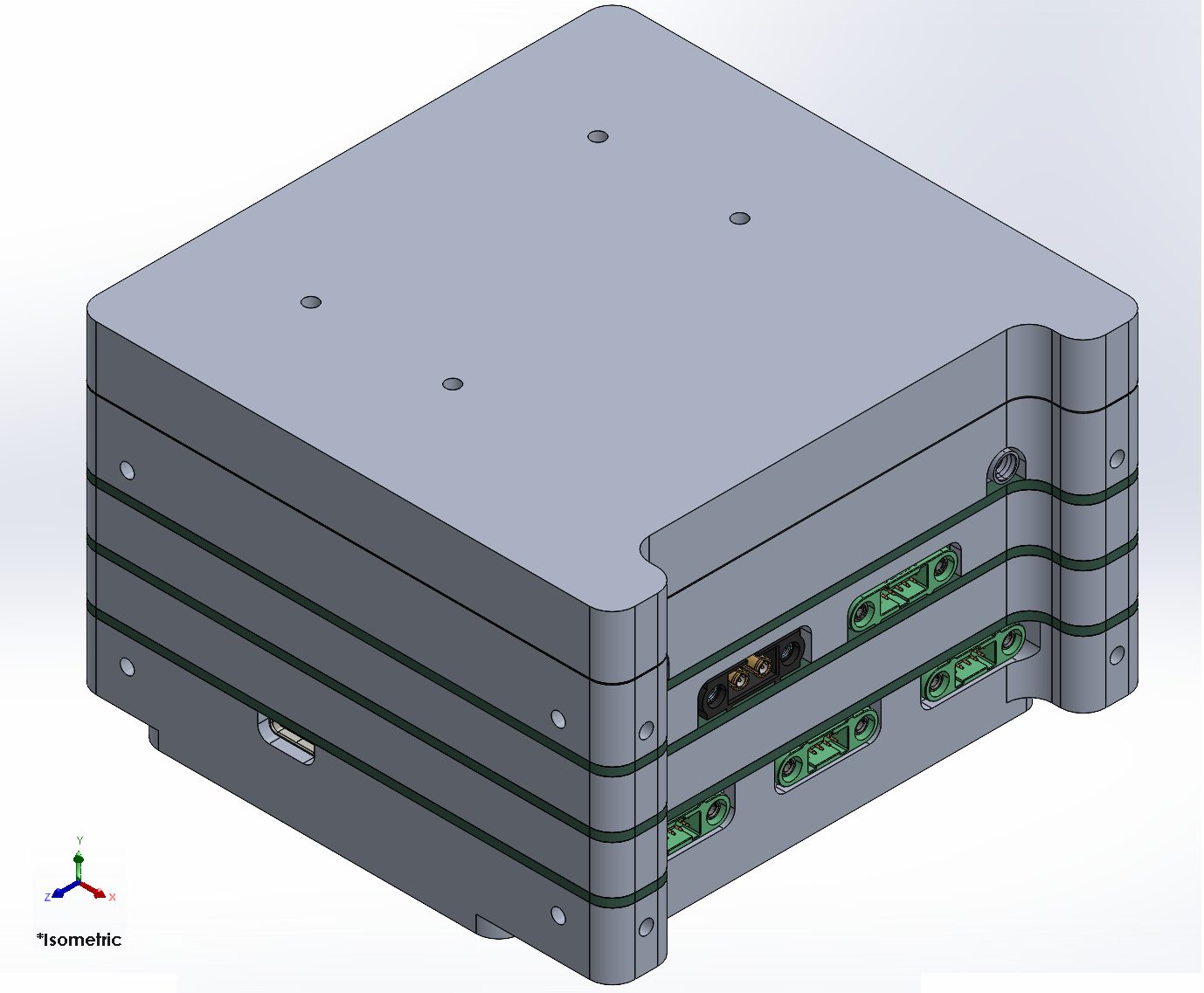
Last month, we gave you an overview of the CubeSat Command Module and its three main subsystems. This month, we’re going one level deeper, into the hardware architecture that makes it all physically possible. How do you fit a capable onboard computer, radio, and power system into a 100 × 100 × 100 mm box? The answer lies in careful and efficient design, making sure that the allotted space is used to its fullest potential.
Coordinate System
Before anything else can be defined, including dimensions, connector positions and mounting interfaces, a common language is needed for describing where things are in space. The Command Module uses the coordinate system defined in the CubeSat Design Specification, with the origin located at the geometric centre of the CubeSat. The X, Y, and Z axes define the three dimensions of the module, and all physical measurements and models are referenced from this point.

Dimensions
The Command Module is designed to fit within a standard 1U CubeSat envelope, which measures 100 × 100 × 100 mm. In practice, the module cannot use every millimetre of that space. The CubeSat itself has its own external walls, each at least 2 mm thick, which reduces the available interior space. This means the Command Module’s dimensions are constrained to a maximum of 95.8 × 95.8 × 95.8 mm (L × W × H).

Interfaces
Connecting all parts of the Command Module to each other and to the rest of the satellite reliably is achieved through a carefully thought-out set of interfaces. These come in three categories: mechanical, electrical, and thermal.
Internal Mechanical Interface
All structural components of the Command Module are assembled using four M2.5 threaded rods, each 57.3 mm long. M2.5 rods were chosen specifically because of the hole sizes in the System-on-Module (SoM), which have a diameter of 2.7 mm, just enough clearance for M2.5. Each rod passes through the entire stack, including all PCBs, and screws into part 01-P01 (the cooler), which has M2.5 threaded holes with a thread depth of 4 mm. On the reverse side, M2.5 DIN 934 nuts secure the assembly.

External Mechanical Interface
The Command Module connects to the wider CubeSat structure through four mounting holes on each of its sides. These holes are threaded for ISO M3 fasteners, with a thread depth of 6 mm and a total blind hole depth of 7.5 mm. The minimum required thread engagement is 3.0 mm, with a recommended range of 4.5 to 6.0 mm for reliable performance.


Internal Electrical Interface
To route signals between the boards within the Command Module stack, four types of SMD connectors are used. At the top of the stack, the SoM carries ADM6-60-01.5-L-4-0-A-TR connectors (240 pins, 60 pins × 4 rows), which mate with ADF6-60-07.5-L-4-0-A-TR connectors on the custom carrier board. This arrangement forwards all SoM pins to the carrier board for further distribution through the stack.
For connecting the middle PCBs in the stack, a second pair of connectors is used: BTH-150-02-L-D-A-K on the top layer (300 pins, 150 × 2 rows) and BSH-150-01-L-D-A on the bottom layer (also 300 pins). A 150-pin version was chosen, larger than the 120-pin minimum, to leave headroom for routing more signals through the bus in the future.
Connectors in the stack follow the naming convention B(i).(j), where B stands for bus, (i) is the bus number, and (j) indicates the vertical layer position between the PCBs.

External Electrical Interface
For connections to other satellite modules, power lines, and RF signals, Harwin Gecko connectors were chosen. These were selected for their small size, proven performance under shock and vibration, reliable operation across a wide temperature range, and low outgassing properties, making them well-suited for space applications near sensitive optical payloads.
The Command Module houses connectors throughout.


The external connectors are:
X1 — SPI and I2C
X2 — CAN0, RS422-1, UART-1
X3 — CAN1, RS422-2, UART-2
X4 — Ethernet
P1 — Power Connector
USB — USB Debug Connector
TX — RF TX Connector
RX — RF RX Connector
Internal Thermal Interface
Keeping the electronics cool in a closed, vacuum-compatible enclosure is one of the tougher engineering challenges of the Command Module design. The Command Module handles this through a layered thermal path: heat generated by the SoM is transferred via a thermal pad to a heat sink, which then passes heat on to the adjacent structural segment through another thermal pad. To maintain good contact, the SoM is pressed firmly against the thermal pad using ISO 4762 M2.5×10 bolts. The other PCBs in the stack make thermal contact with the aluminium structure along their edges, providing passive cooling.


External thermal Interface
For the thermal interface material itself, the team evaluated several space-rated options and found that the BERGQUIST® GAP PAD® TGP HC5000 best matches the requirements: it is electrically isolating, can be verified in the NASA outgassing database, and has a thermal conductivity of 5 W/mK with a volume resistance of 10^10 Ohm·m.
The Command Module also features two external thermal interfaces. Depending on its position within the CubeSat, heat is transferred through either the upper heat sink surface or a side heat sink. In both configurations, a thermal pad is installed between the thermal interface and the radiating plate to minimise contact resistance. Threaded holes adjacent to each interface allow controlled fastening and uniform compression of the thermal pad.


Structure
The structure of the Command Module serves as the backbone that holds everything together and protects the electronics from radiation and excessive heat. The most important structural requirements include: keeping all components fixed and in place, passing vibration tests, dissipating heat away from the PCBs, making connectors accessible for integration, and fitting within the 1U CubeSat mass and size budgets.
A conformal coating, ABChimie 526UV, will be applied to the PCBs to reduce wear and extend their lifespan. This UV resin is cured using an LED or mercury lamp at 395 nm wavelength, with a minimum UVA dose of 3000 mJ/cm², a coating thickness of 100 µm, and a minimum UVA power of 500 mW/cm².
The hardware architecture of the Command Module consists of several constraints: it has to fit within the standard 1U size, survive launch vibrations, stay cool in the vacuum of space, and to connect everything within the satellite reliably. Therefore meaning every millimetre and every connector is deliberately chosen.
Next month, we will be going even deeper into one of the Command Module’s core subsystems. Stay tuned!
Leave a Reply